Review of HackerBox 0122 - Ouroboros
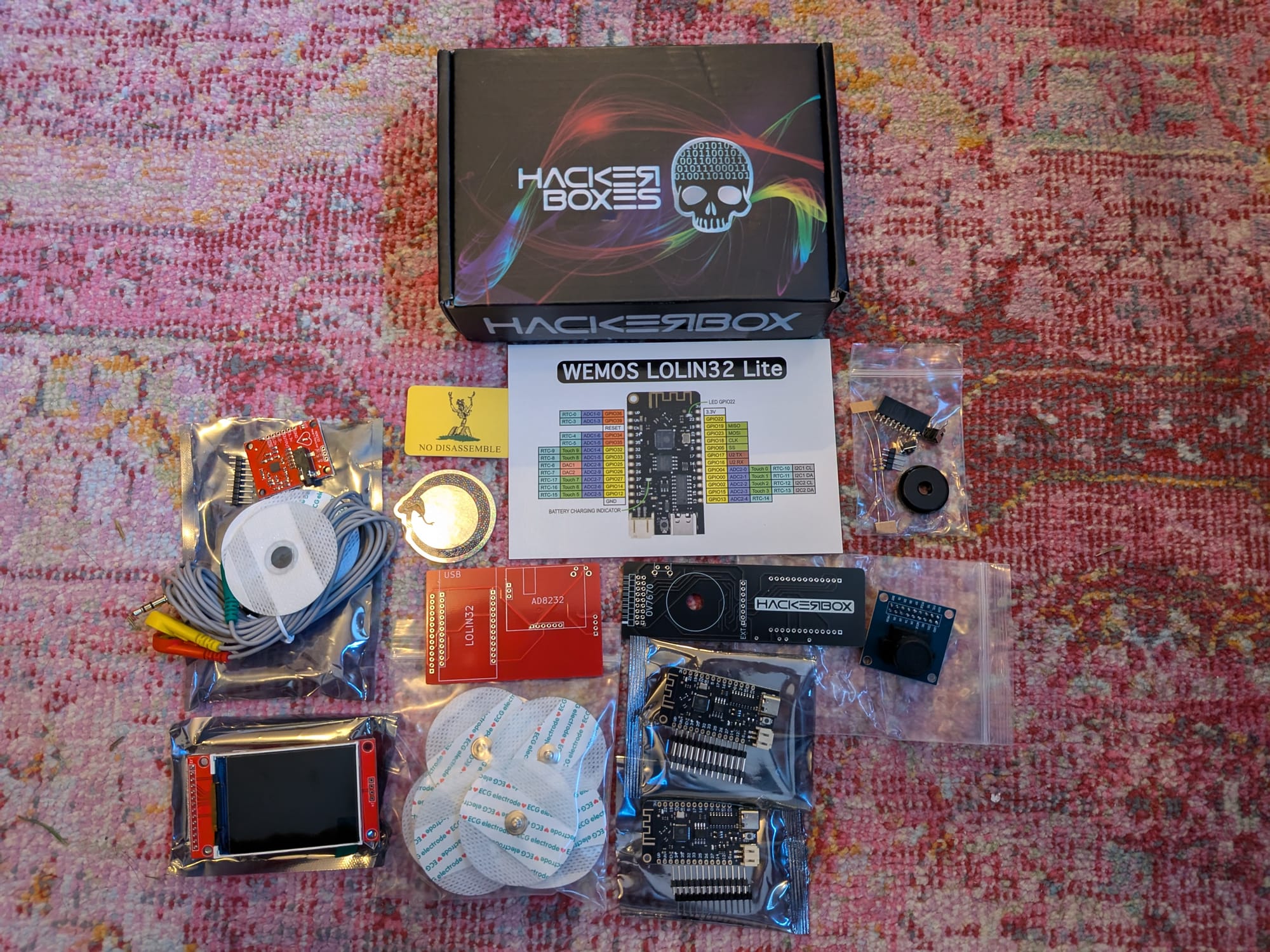
I think the HackerBox creators must stalk me. This month's box has a camera, and an ECG kit! I haven't written about HRV analysis yet, but it was a past hyper fixation of mine.
Which reminds me of a recent episode on medical electronics from the Amp Hour podcast. In the episode Dr Palmeri talked about using Zephyr in his classes as an alternative to Arduino. As I mentioned in my post about learning Rust, I appreciate having alternatives to Arduino given the current events.
As always, the official instructions are up on the Instructables guide.
More bench tools for the tools god
I am a tough person to buy gifts for. I'm trying to buy less physical stuff and I'm also the kind of person that will buy something right away when I truly need it.
When I got into HackerBoxes over the last year I picked up just the essentials I needed for soldering. I've held off on the nice to haves and instead put them into a gift list for family members. [1]
Anyways, I received some nice new tools and they certainly made assembly go smoother this month. The item I wanted most was a box of task wipes for cleaning flux off PCBs. I should have realized that to someone who doesn't work with electronics, that would seem like the least important item on the list, so I had to buy that for myself. [2]
Outside of the wipes I also got some acid brushes to help with cleaning the board [3], some helping hands and a solder sucker[4].
Now I have a new problem: how on earth to store an organize all this stuff. Alas, I'll figure that out another time.
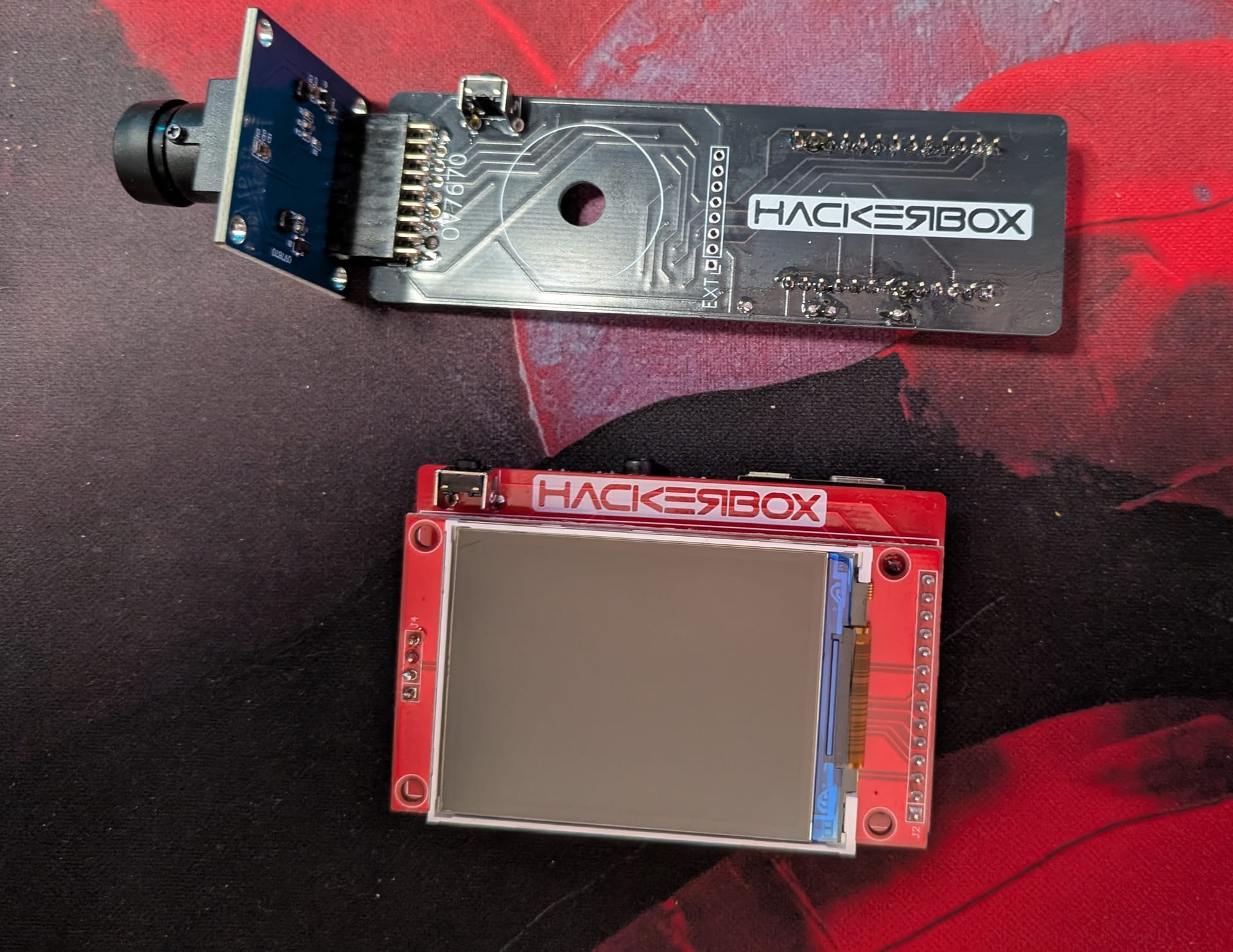
Assembling the OVcam
Big bold warning to take your time and read carefully on this months box.
Thankfully there was much less soldering this time vs last month's HackerBox 0121 - MCU Lab, which had so many parts that I ended up soldering the SD card slot upside down.
Here's the soldering details for this half of the kit. Remember, think of this less as instructions, and more as a quick measure of effort to compare the monthly kits.
For the OVcam:
- Solder the right angle 2x9 pin female header to the top. [5]
- Solder the right angle tactile pushbutton to the top.
- Solder the two 1x13 pin male header to the ESP32 WeMos LOLIN32 Lite.
- Solder the ESP32 to the bottom of the board.
- Solder two 4.7K resistors to the board.
The OV7670 camera module goes into the female header so there is no soldering for that.
This is the first time the I've gotten a HackerBox that included resistors. Thankfully they are both 4.7k, so I don't have to think about resistor color codes like I did in the electronics class I took. I eventually learned they are for keeping the clock and data pins for i2c pulled high. This led to some reading that really helped me better understand i2c:
- The lines are open drain - so attached components are able to pull the line low, but not high. Something else is needed to keep the line high.
- Each bus on i2c has its own pull-up resistor connected to the voltage supply that make the pin read high by default. 4.7k resistors are considered a good starting point.
- The lower the resistance, the faster the line will return to high.
- This ensures that the pins clearly reads high or low and do not float.
Also, this was my first time soldering a right angle header. This video guide shows how you can solder one pin from the top and adjust the alignment before flipping and getting all the pins from the bottom. The video also has the bonus tip for clipping headers: clip the headers into a bag so they don't fly off to the other side of the room.
Notably, there are 8 holes in the middle of the board labeled "EXT" that are not used:
 [6]
[6]
They are there if you want to attach a TFT display.
The OVcam software
Even though the sketch for this project includes a web server, it is very different from my self hosted dog camera. After all, there is no dedicated video acceleration hardware on this board, so the framerate can only go so high.
The project is based off this ESP32CameraI2S project. The Instructable doesn't mention, but the repo has a video explaining how the project works. He mentions the SCCB (SCL) and SCCB (SDA) [7] pins for i2c. I talked about i2c before in HackerBox 0120 - current affairs and my post on the ESP32 based beaconDB scanner. I also recently found this great written guide to i2c on sparkfun.
That project is based off an even older project esp32-cam-demo from someone at expressif. They provide a approach for transferring the frames without FIFO using i2s parallel mode. The readme also include a nice table explaining the pin out.
Putting all that info together here, this how I think parallel mode works:
- As mentioned, XCLK is used for providing the clock to the camera. Instead of using an oscillator, the project uses LEDC, the LED control from the ESP32, to send a 20mhz signal.
- The horizontal sync, vertical sync, and pixel clock all work together to control when i2s will push new data into memory using parallel mode.
- Horizonal reference (HREF) is sent when a line is ready and vertical sync (VSYNC) when a new image is ready.
- There are also 8 pins for pixel data and a pixel clock PCLK pin which is sent when the next byte of a pixel is ready.
- They use two DMA buffers in a ring. When one fills there is an interrupt to signal to read a buffer, and the other buffer will start to be filled.
- Those buffers are read into the frame buffer.
This is a great video explaining Direct Memory Access (DMA) and how DMA allows the CPU to step out of the way of an I/O device writing into memory. This is done using a dedicated controller that handles moving the memory. The preceding video on interrupts is also useful.
Getting the OVcam code working on the new version of ESP-IDF
GenAI Callout: I used Claude Code to help me learn about the project and bounce ideas / build errors off it. I made sure to prompt Claude to not make code changes, but instead to help me understand what changed between the library versions.
The guide mentions:
Part of the migration from 2.x to 3.x involved a change in the LED Control (LEDC) API to support the Peripheral Manager. LEDC is use in the bitluni project to generate an XCLOCK signal supplied to the camera module. It should be fairly straight forward to update the LEDC functionality to work with the latest ESP32 board package. Should you wish to take on that mission, please share your results with the rest of us.
I gave it a try and was able to get everything to work!
In ESP32_I2S_Camera/I2SCamera.h I needed to update headers as various pieces were moved around in the library upgrade:
 #pragma once

+#include "esp_attr.h"
+#include "rom/gpio.h"
 #include "soc/soc.h"
 #include "soc/gpio_sig_map.h"
 #include "soc/i2s_reg.h"
 #include "soc/i2s_struct.h"
 #include "soc/io_mux_reg.h"
+#include "soc/gpio_struct.h"
 #include "driver/gpio.h"
-#include "driver/periph_ctrl.h"
+#include "esp_private/periph_ctrl.h"
 #include "rom/lldesc.h"
 #include "XClk.h"
 #include "DMABuffer.h"
In ESP32_I2S_Camera/XClk.cpp I had to update a header since some methods were moved into a private header. I also had to add a memset call to clear timer_conf before using the structs as per this issue. Finally, the bit_num field on the configuration was renamed to duty_resolution so I updated that as well.
 #include "XClk.h"
 #include "driver/ledc.h"
+#include "esp_private/periph_ctrl.h"
+#include <cstring>

 bool ClockEnable(int pin, int Hz)
 {
     periph_module_enable(PERIPH_LEDC_MODULE);

     ledc_timer_config_t timer_conf;
-    timer_conf.bit_num = (ledc_timer_bit_t)1;
+    memset(&timer_conf, 0, sizeof(ledc_timer_config_t));
+    timer_conf.duty_resolution = LEDC_TIMER_1_BIT;
     timer_conf.freq_hz = Hz;
     timer_conf.speed_mode = LEDC_HIGH_SPEED_MODE;
     timer_conf.timer_num = LEDC_TIMER_0;
Here is the commit in my fork.
Also, I believe the new version of ESP-IDF has a totally different and cleaner way to set up LEDC, but I avoided this since I wanted to keep the new code as close to 1:1 as possible.
Somewhat related, I also found a discussion on porting the Arduino camera and display ecosystem to Zephyr. They aren't there yet, but are making progress.
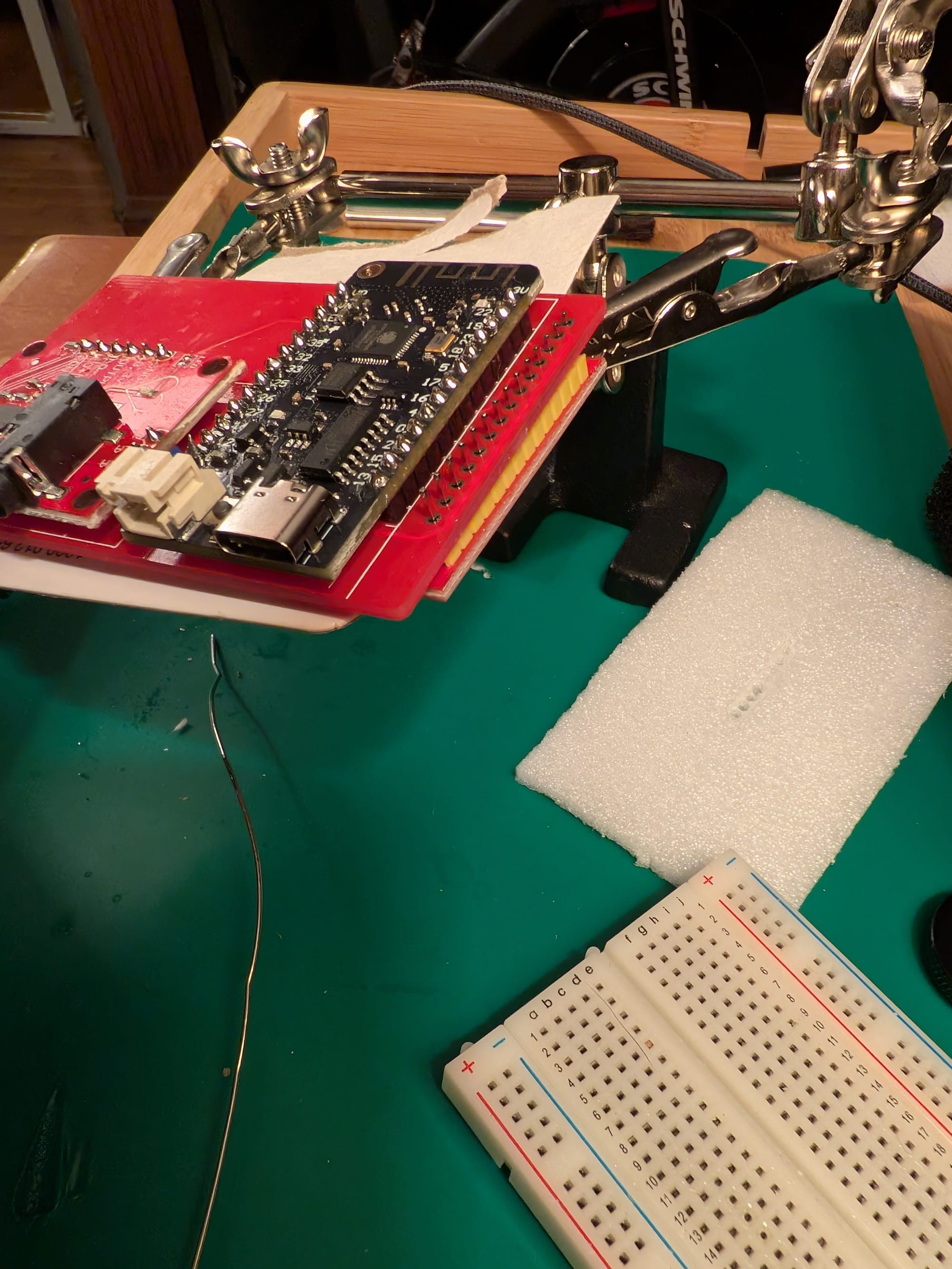
Soldering the ESP ECG
The section was very complicated and I'm happy I took my time:
- Solder the right angle tactile push button onto the side of the PCB with "HACKERBOX"
- Trim the leads. There will not be much clearance between the stacked PCBs.
- Solder the two 1x13 pin male header to the ESP32 WeMos LOLIN32 Lite.
- Solder the ESP32 to the bottom of the board.
- Trim all the leads.
- Break the 1x9 pin male header into a 1x3 pin and 1x6 pin.
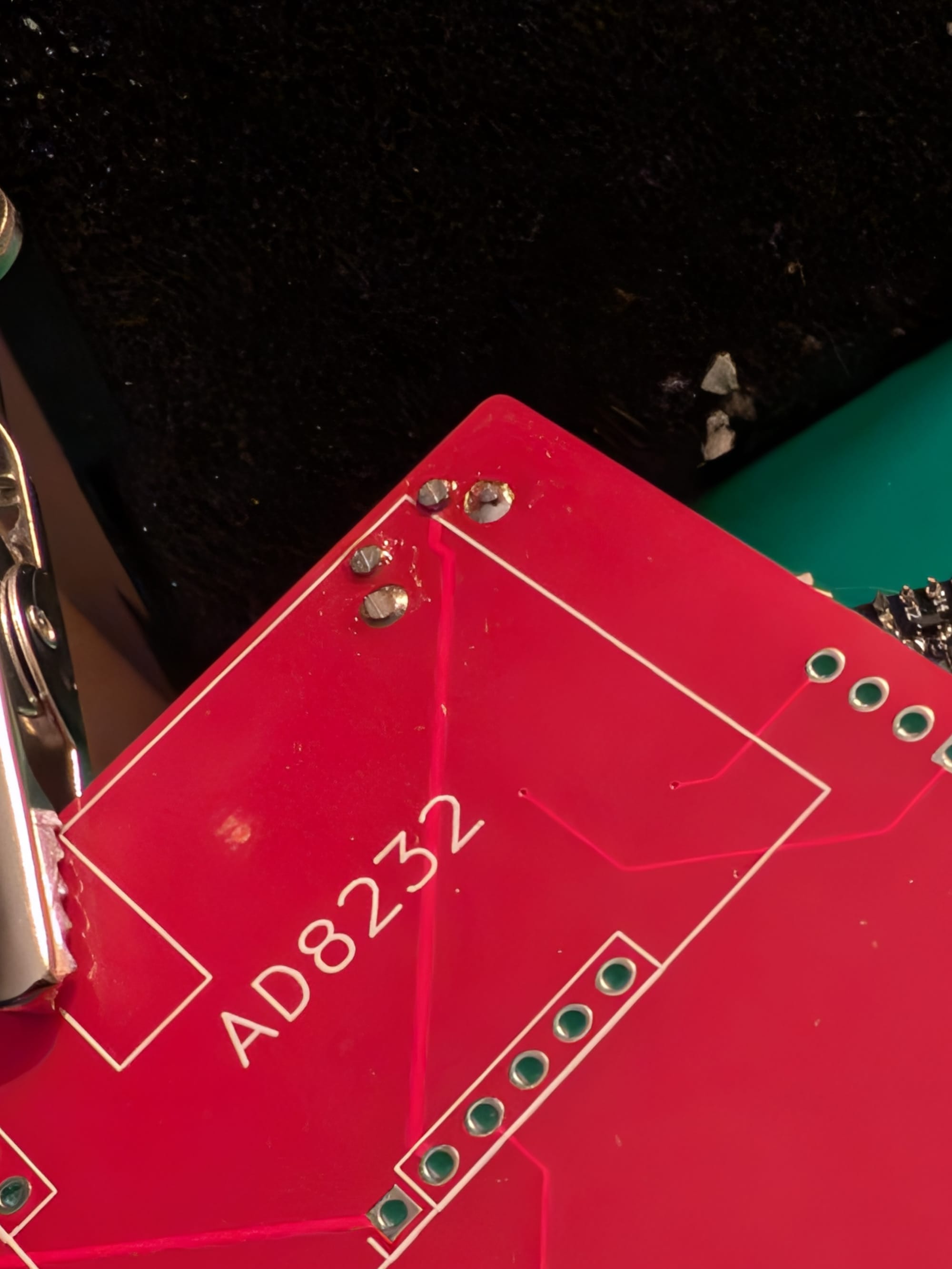
- Solder two 1x3 and 1x6 pin headers onto the AD8232 ECG Sensor Module.
- Solder the sensor module onto the back of the board.
- Trim all the pins.
- Solder the 1x4 pin male header to the MSP2401 display module.
- Solder the display module to the ESP ECG PCB.
- Make sure to keep a little space between the two boards. I temporarily inserted thick piece of paper and use helping hands to stabilize.
Here's an example of the trimmed leads:
Here's the spacing for the two PCBs:
Inspired by the header cutting idea, I put the board and my hands inside of a gallon freezer bag and trimmed all the pins so they would not fly everywhere. This worked surprisingly well, though I assume there is a better more standard way to do this.
Using the ECG
I don't have a formal background in signal theory, but last year I read a bit of Understanding Digital Signal Processing by Richard G. Lyons to learn some basics when I was messing around with HRV measurement. In that scenario I was looking into PPG, which is optical, rather than ECG. Marco Altini does a lot of excellent writing on this in his Substack.
The guide describes the AD8232 as a "integrated signal conditioning block" that helps measure small biological signals under noisy conditions. The instructables also links to this guide on the AD8232 which was very thorough and I recommend reading.
The pin out analysis:
- The OUTPUT pin is an analog signal of the boosted and cleaned up HR.
- LO- and LO+ are used for detecting if the electrodes are off the body.
- RA, LA and RL are used for Right Arm, Left Arm and Right Leg electrodes in a different setup without using the 3.5mm jack.

The electrode placement in Einthoven's triangle.
I like HR devices a lot. As I mentioned in my post race report, they are useful for estimating load and recovery to prevent over training. At any moment in time I typically have between two and five HR devices on me:
- A strap that measure recovery on one wrist.
- A watch that's more specialized for running on another wrist.
- When I'm exercising I'll put on a chest strap.
- Sometimes other devices I'm testing and comparing. [8]
Outside of a quick test with this ECG I didn't do much more with it yet. In the future I might try to compare the signal with a reference device to see how accurate it is.
I also directed them to not give me physical gifts if possible, but many people still wanted to give something, so I made a list. ↩︎
I kept doing HackerBoxes over the months thinking, man I'm excited to get my task wipes since this paper towel isn't doing it. ↩︎
You can cut the bristles shorter to make them easier to use. ↩︎
Which saved my bacon on the ECG build in this months box ↩︎
The top side of the PCB says "HACKERBOX". ↩︎
I had to look up the symbol since I had not seen it before, but the right angle under the left most pin is a pin 1 indicator. ↩︎
As I had mentioned in a previous review, there is great inconsistency in i2c pin naming. ↩︎
My Pebble should be shipping soon. ↩︎
Member discussion