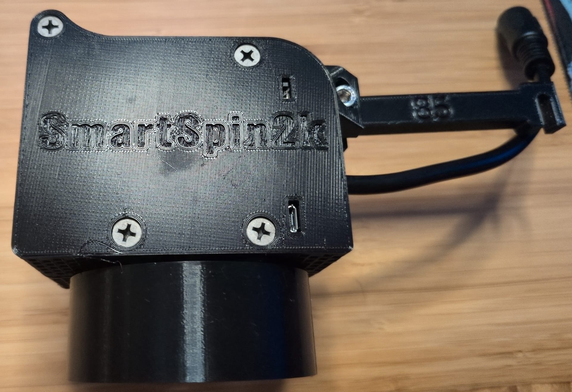
Assembling and Testing the SmartSpin2k On A Schwinn IC4
Gathering the full parts list
This is a follow up to my previous post about printing all the parts for a SmartSpin2k. Now that I had everything ready, I could finally get to assembling.
The SmartSpin2k wiki has a nice parts page that I used as a reference. There are three broad categories or parts for this build:
- The 3D printed pieces.
- The electronics.
- The mechanical parts.
To quickly recap the 3D parts, I had to print:
- The left and right halves of the main body.
- Two spur gears.
- A window piece. [1]
- A mount specific to my bike. [2]
- An arm that connects the mount to the body.
- A cup fit for the specific resistance knob on my bike.
- An insert that connects the motor to the cup knob.
I did not print out the case for the shifter, since that requires printing with TPU. [3]
For the electronics:
- I bought this PBC + wiring harness kit off of Etsy... last year. It's been sitting in my closet for a while. Also, oddly enough, the listing no longer shows all the parts I received. My kit also contained the remote for gear shifting and the cable for the remote.
- 38mm NEMA 17 Stepper - I ordered the one linked in the guide, however that link now seems to point to a laser engraver?
- I did not have to order the Stereo RCA to 3.5mm headphone "Y" Cable, because there was one included in the PCB kit.
- 12v power supply - I ordered the one linked in the guide.
For the mechanical parts, I ordered the following online:
- 608 Skate Bearings - I accidentally ordered 16 of these. The project requires 2. So if you want any, please message me and I will mail them to you.
I was able to obtain the remaining mechanical parts from my local ACE hardware. However, the recommended hardware page does not list everything that was needed. So I ended having to take two trips to the store...
The complete set of the hardware store parts are:
- 1 x 5/16" x 1-1/2" Hex Head Bolt - for connecting the insert to the larger spur gear.
- 2 x 5/16” Hex Nuts
- 5/16” Flat Washer
- 4 x 2” Black Oxide Sheet Rock Screws - the only ones I could find were threaded all the way to the top. They also didn't really sink well. The M5 Screw helped keep it together though.
- 2 M5 X 30mm Cap Screw (or #10x1.25”) and the appropriate nut
- Zip ties
Putting the body together
There are build instructions for the V3 case. Specifically, the SS2kR3BuildingInstructions.pdf is what I used.
The rough flow of the process is:
- Assemble the axle.
- Put the stepper motor, axle, wire, and PCB into the left side of the case.
- Screw the two halves of the case together.
- Attach the arm to the case.
- Attach the mount to the bike with a zip tie.
Some notes from the process:
#1 My stepper motor size was different
The instructions depict the stepper motor fitting like this:
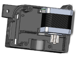
However the motor I received had a flange at the base of the D shaft which prevents the gear from sitting flush:
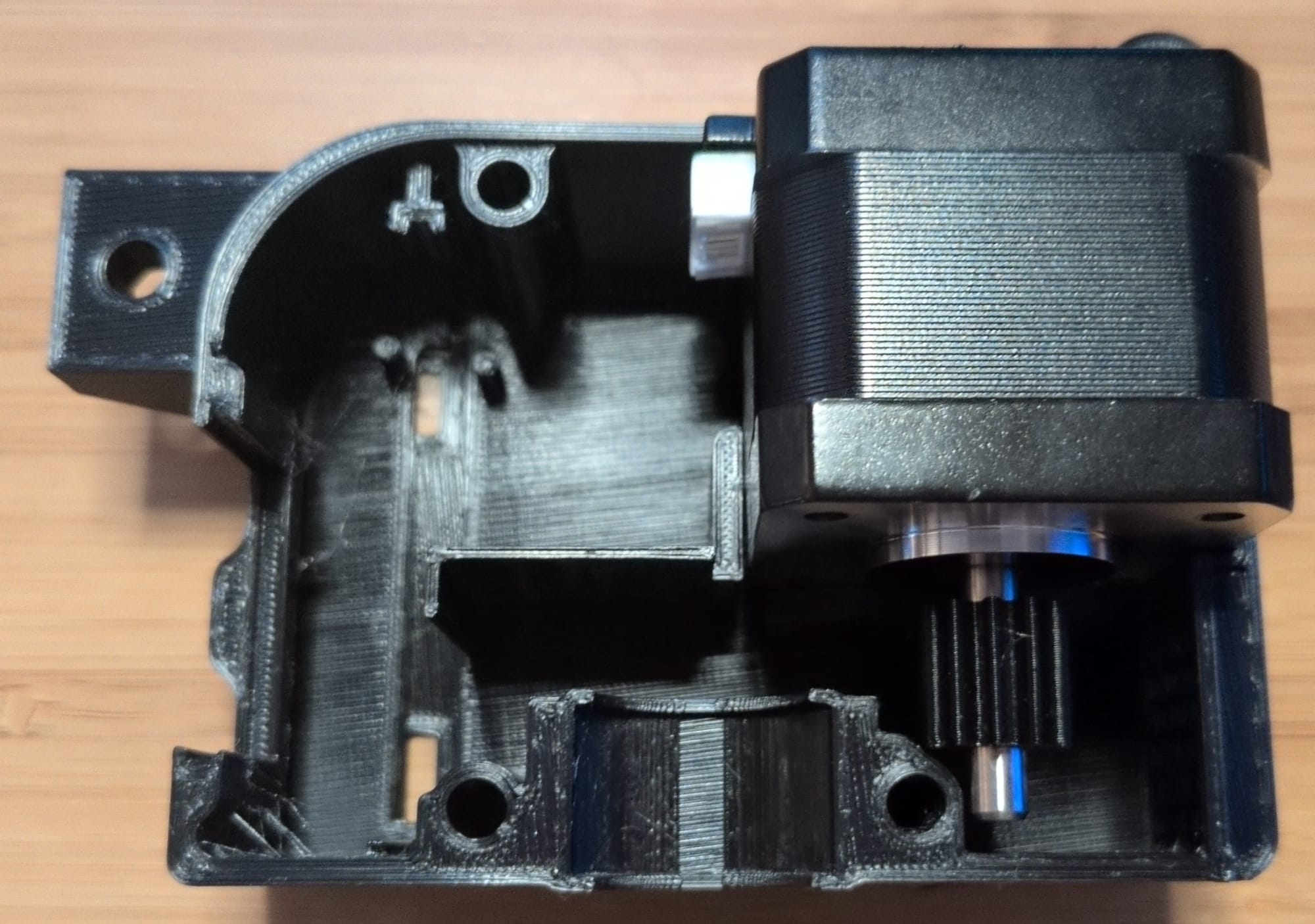
This leaves a very small amount of clearance between the spur and the case.
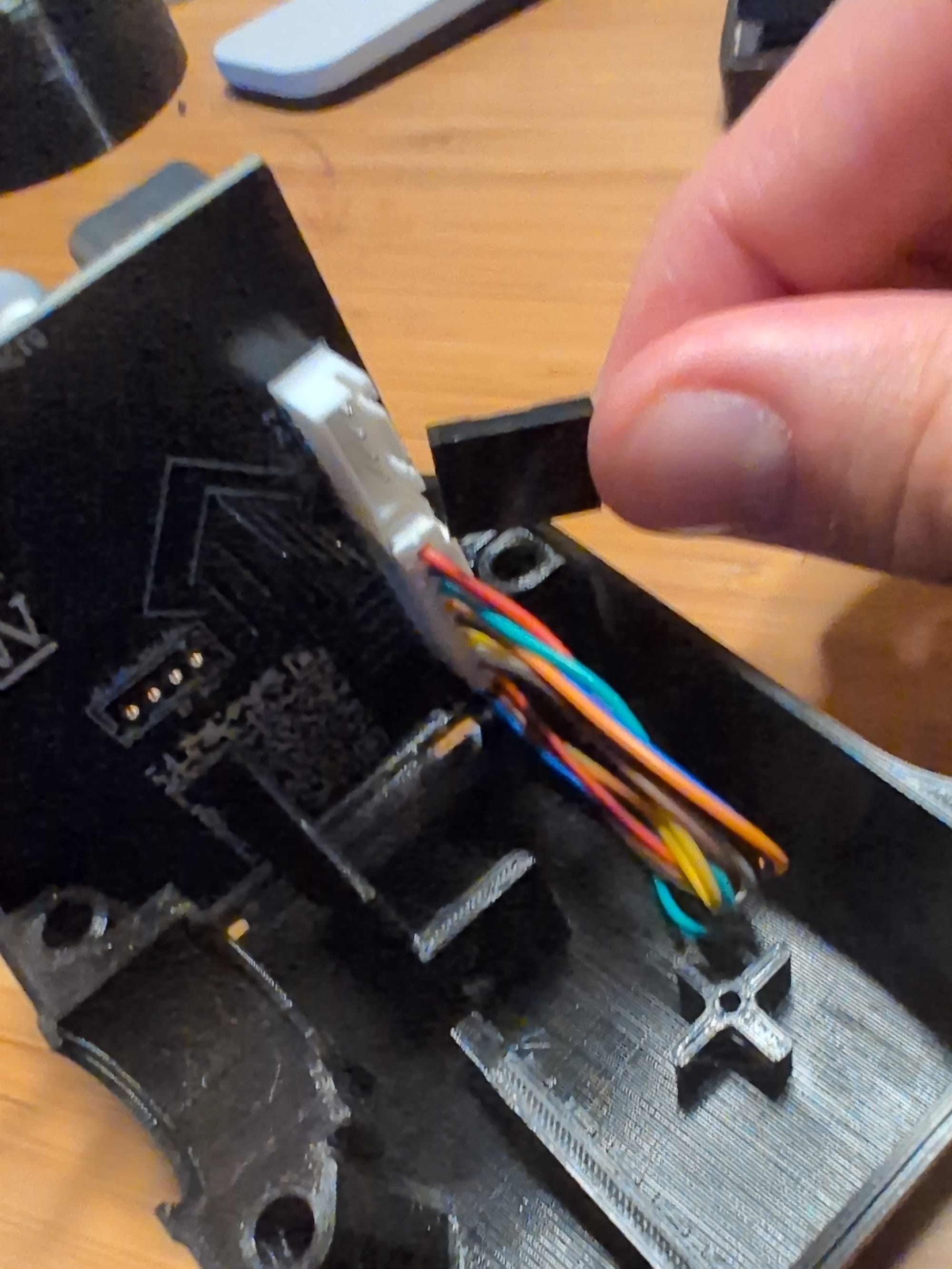
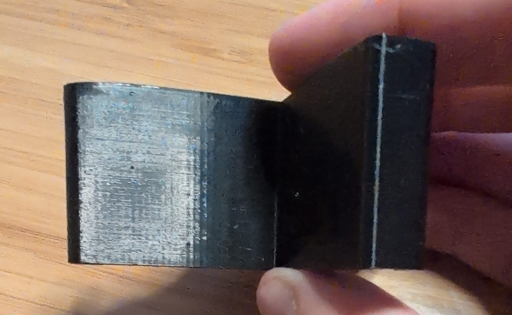
#2 My stepper motor cable was different
If I'm getting the terminology right, the PCB is designed to use a JST connector for connecting the stepper motor. However, the cable off of the stepper motor just uses simple female pins:
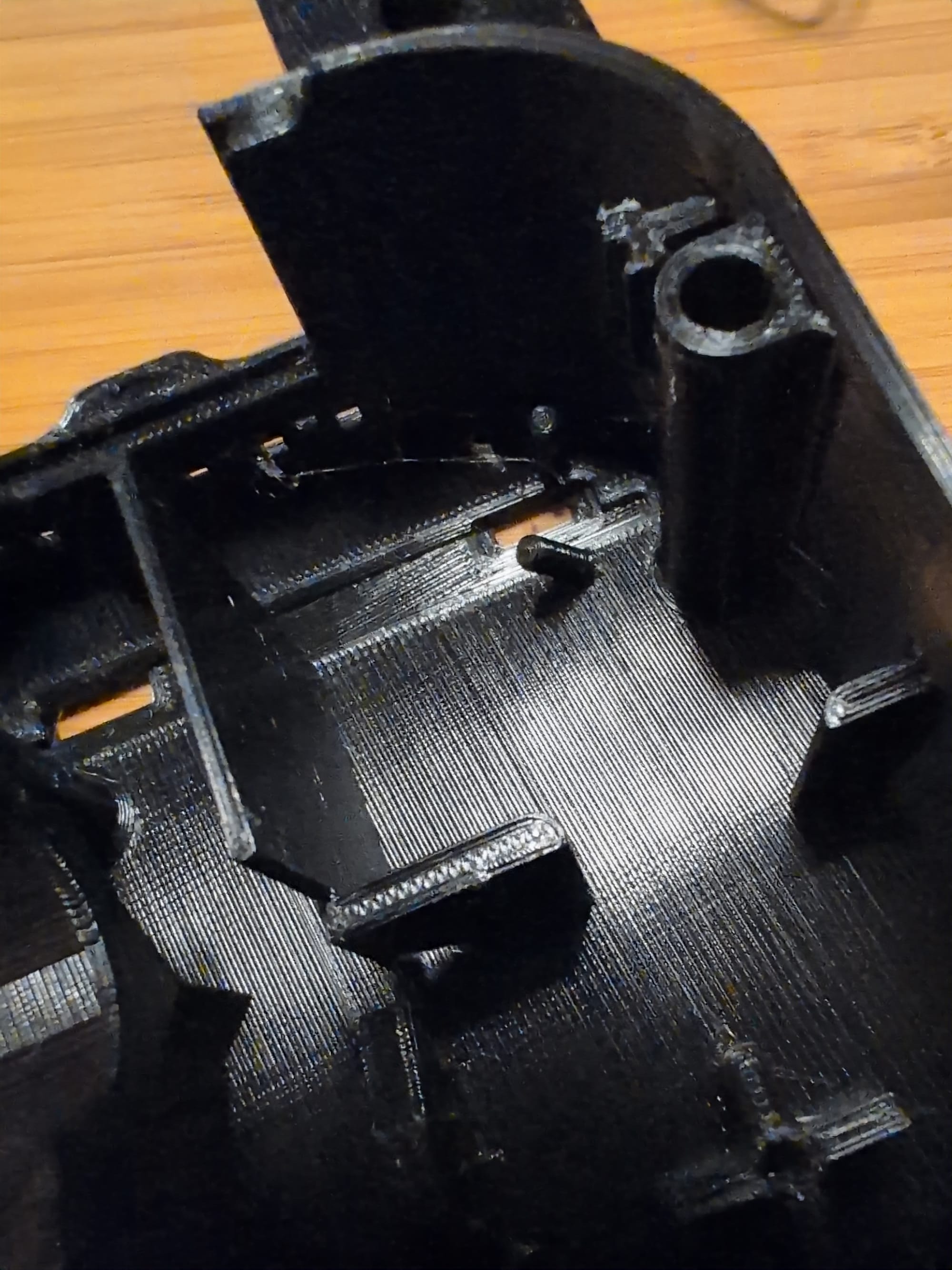
#3 My PCB cable was different
There is a small plastic stud in the case that is supposed to keep the PBC cable in place. My cable seemed a little thicker than what the design expects so the pin broke almost immediately:
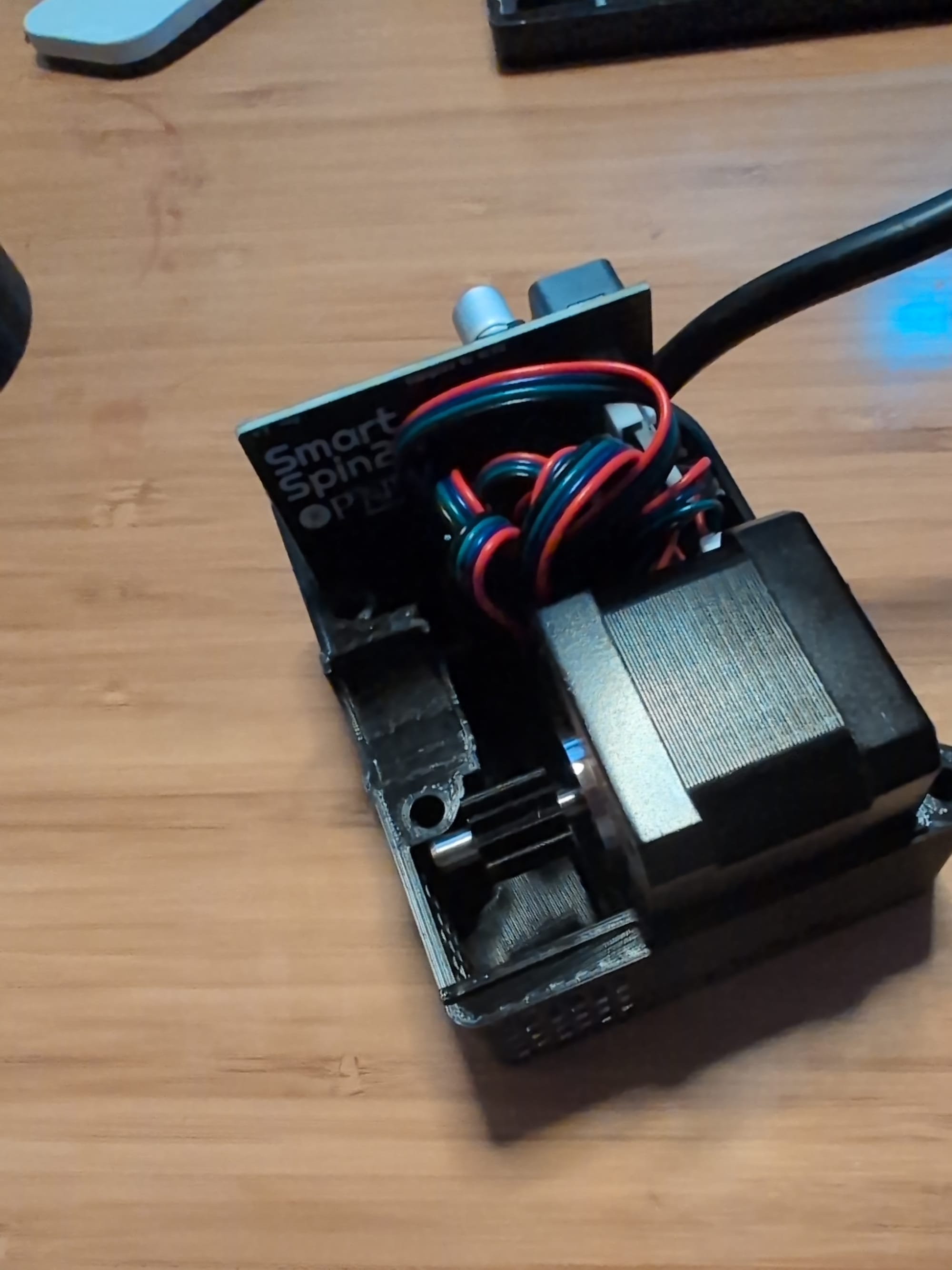
#4 My stepper motor cable was different yet again
The stepper motor came with a very long cable:
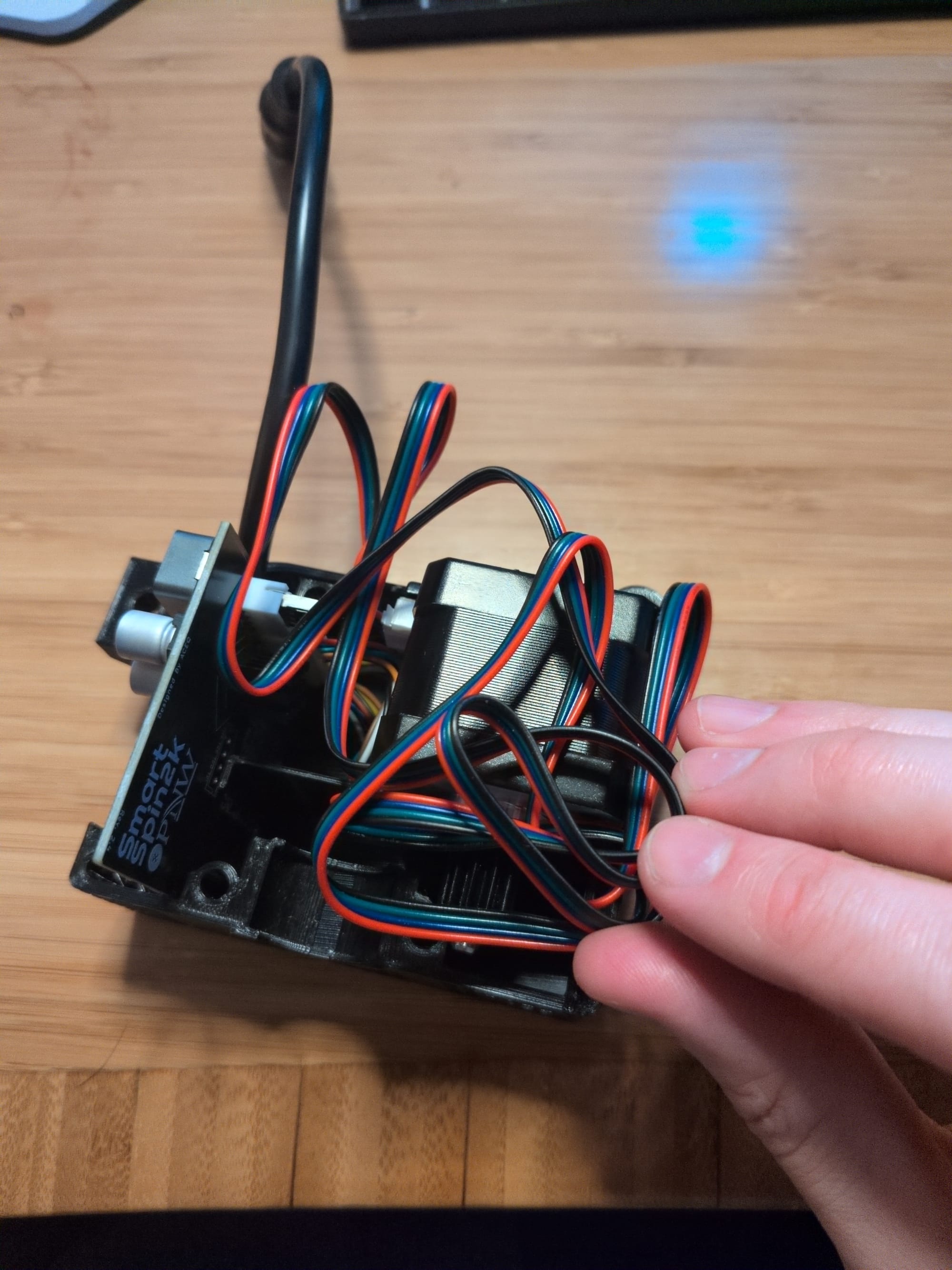
But with some patience I was able to fit everything without bending the connectors:
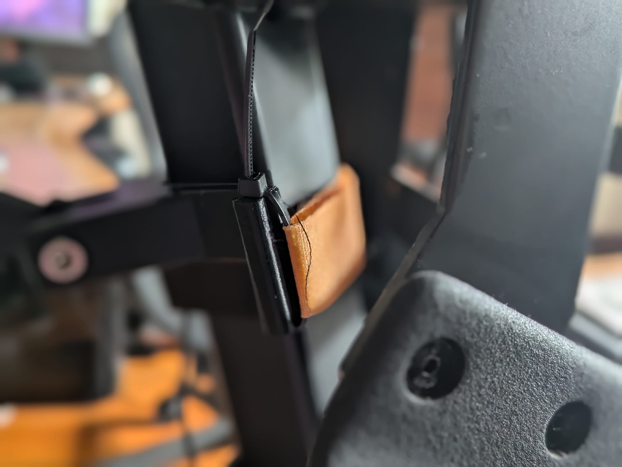
#5 My mount was different
The instructions show the bike mount having holes that you can zip tie through:
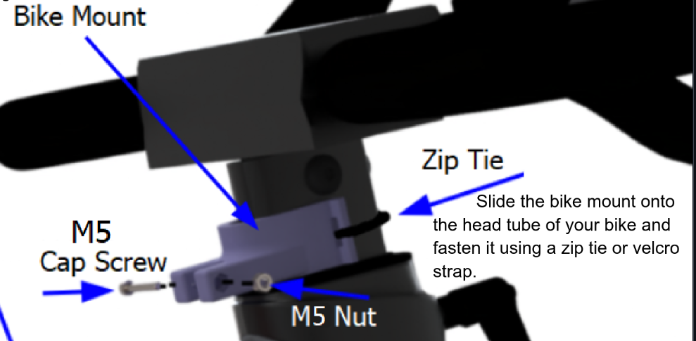
However the file I printed did not:
So I had to zip tie both sides, and then strap the mount on using a velcro strap I had:
#6 Some 3D printed pieces didn't fit well
The hex nut had a hard time fitting into the knob cup since the hole was not chamfered. The nut finally fit through after some sanding.
The 11 tooth spur had a hard time sliding onto the stepper motor. My friend recommended using a hair dryer to warm the spur. That did not work for me, but I heated water in my kettle to 78 C and submerged the spur. That did the trick!
It turns out if I had read the instructions more carefully I would have seen:
Depending on printer tolerances, you may need to heat the gear to prevent damaging it.
Finally, the cut out in the window was not big enough for the diameter of the cable in the kit.
Companion app and software
There is a companion app [4] that can connect to the SmartSpin2k over WiFi or Bluetooth. My PCB came with a firmware installed, but I had version 24.10.14-develop installed so I updated using the app to the latest firmware which was 25.9.30. Also, I should note that the app failed to connect over WiFi but "fell back to Bluetooth". The whole update process took about 2 minutes.
Installing and running
There are installation instructions with very clear GIFs. So I set everything up and it worked perfectly... I wish.
Instead, I started the homing procedure. The SmartSpin is supposed to home to minimum resistance, detect when the knob stops, home to maximum resistance, detect when the knob stops and then return to 0. In my case the device homed to max resistance on the bike, but acted as if it was 0 resistance. When I tried to control the SmartSpin2k it proceeded to spin backwards and unscrew the axle.
I thought I had reversed the wires on the motor, but after double checking everything I confirmed the wiring was correct. After some reading I saw there was configuration option "Stepper Motor Direction":
This setting controls the orientation of the motor and the direction it turns. Depending on how your motor is wired, this may need to be toggled.
"May need to be toggled" indeed. Oddly enough, all of the other configuration options can be set through the app, except for this option. Instead you have to configure WiFi to connect to your AP and then access the web interface. The documentation says you can use the hostname smartspin2k.local, however that never resolved for me. Instead I had to go into Opnsense and find the IP address for the device.
My first ride
The SmartSpin2k website lists the compatible training programs. However, I don't bike using any bike simulators. Instead, as I mentioned in my Boston Run to Remember Half Marathon race report, I use Qdomyos-Zwift on my phone with an ANT+ usb stick.
As per the first ride instructions, you want to power on your bike first since the device will automatically connect to the bike over Bluetooth when powering on. Then I simply had to:
- Switch QZ to connect to my SmartSpin2k instead of my IC4 bike.
- Under "Accessories", I set the SmartSpin2k device setting in QZ to enabled and selected my device.
- Made my Garmin watch search for more devices and detect the new "trainer" type accessory.
Then I tried to go for a ride! My Daily Suggested Workout was sets of 10s sprints with 2 minute rests.
With the default settings, the bike barely got up to target resistance by the end of the sprint. In the app settings you can change the "ERG Sensitivity" setting:
This setting adjusts the aggressiveness of the ERG. This can be adjusted from 1 to 20. Too low will cause the ERG to be slow at reaching the target wattage. Too high will cause it to overshoot too far and miss the target in each direction before it settles. A good starting value is 5. A little bit of overshoot is okay if it settles on the target output quickly.
I changed this to 9 and it ramped up much quicker. I wish there was a way for the bike to start ramping a second or two before the interval starts, but could not find an option.
Final thoughts
Projects like this can be janky. Projects like this can take a while to get working. Projects like this are not as simple to operate compared to a ERG you might buy. You know what though? I was able to build all of this using open designs and I saved a lot of money along the way. Plus, this is a device I can control. If you just want to go ride, probably don't build a SmartSpin2k. Do you want to avoid Peloton forcing a $95 activation fee on used bikes and increasing subscription fees?
I don't know what the long term durability of the SmartSpin2k will be, but because I put the device together, I know how to repair it when it breaks. Ultimately, if you want to stop buying new stuff, make old stuff work and tinker than give this project a go!
I did not have any clear filament to use, so mine was less of a window and more of a side cover. ↩︎
Which is a used Schwinn IC4. ↩︎
Also, it seems there are files for both "PCB Shifter" and a "Hand wired Shifter". For the kit I bought, I would need the former and not the latter. ↩︎
Which oddly enough doesn't seem to be open source? ↩︎
Member discussion