Review of HackerBox 0120 - Current Affairs
Another month, another post as a part of my HackerBox review series. This time I received HackerBox #0120 - Current Affairs. Here are the Instructables instructions for this box. The write up is shorter this month since I was not able to do all of the steps.
The frontmatter
The guide had a nice summary of how voltage, current and resistance are all related. I took an introduction to electronics course last month at Artists Asylum, and appreciated a refresher. I never took an electronics class in school, but both the course and this guide used water in pipes as a metaphor, so that must be a pretty common explanation.
The guide then talked about using a root mean square [1] to measure AC currents and why RMS is needed to find the average current. Notably though, there is no description of AC vs DC currents. This brief video provides a simple overview.
The guide also mentioned the board we will use only makes discrete measurements and not continuous measurements, but doesn't go into more details. This post on the blog Statistics By Jim explains the difference.
Then there is an explanation of a how a current transformer works and the first safety warning of the guide. The guide had many safety warnings. The guide also directed me to slice open an extension cord:
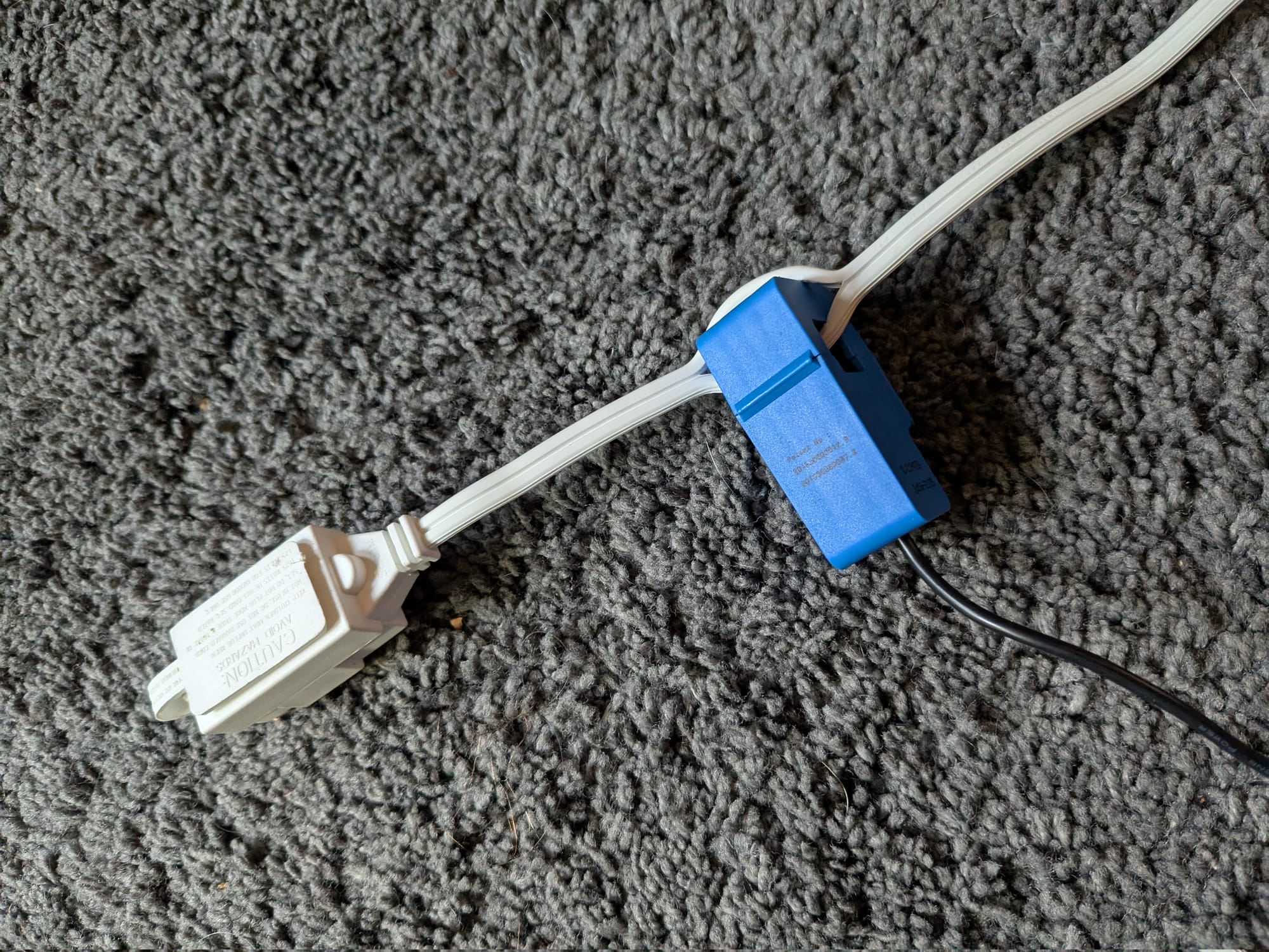
Ironically, I've made sure to replace all my janky, old, ungrounded extension cords with higher quality surge protectors and extension cables. Thankfully, I was able to find in my storage an older style extension cord like the one depicted in the guide for sacrifice.
Assembling the Current Affairs Power Monitor
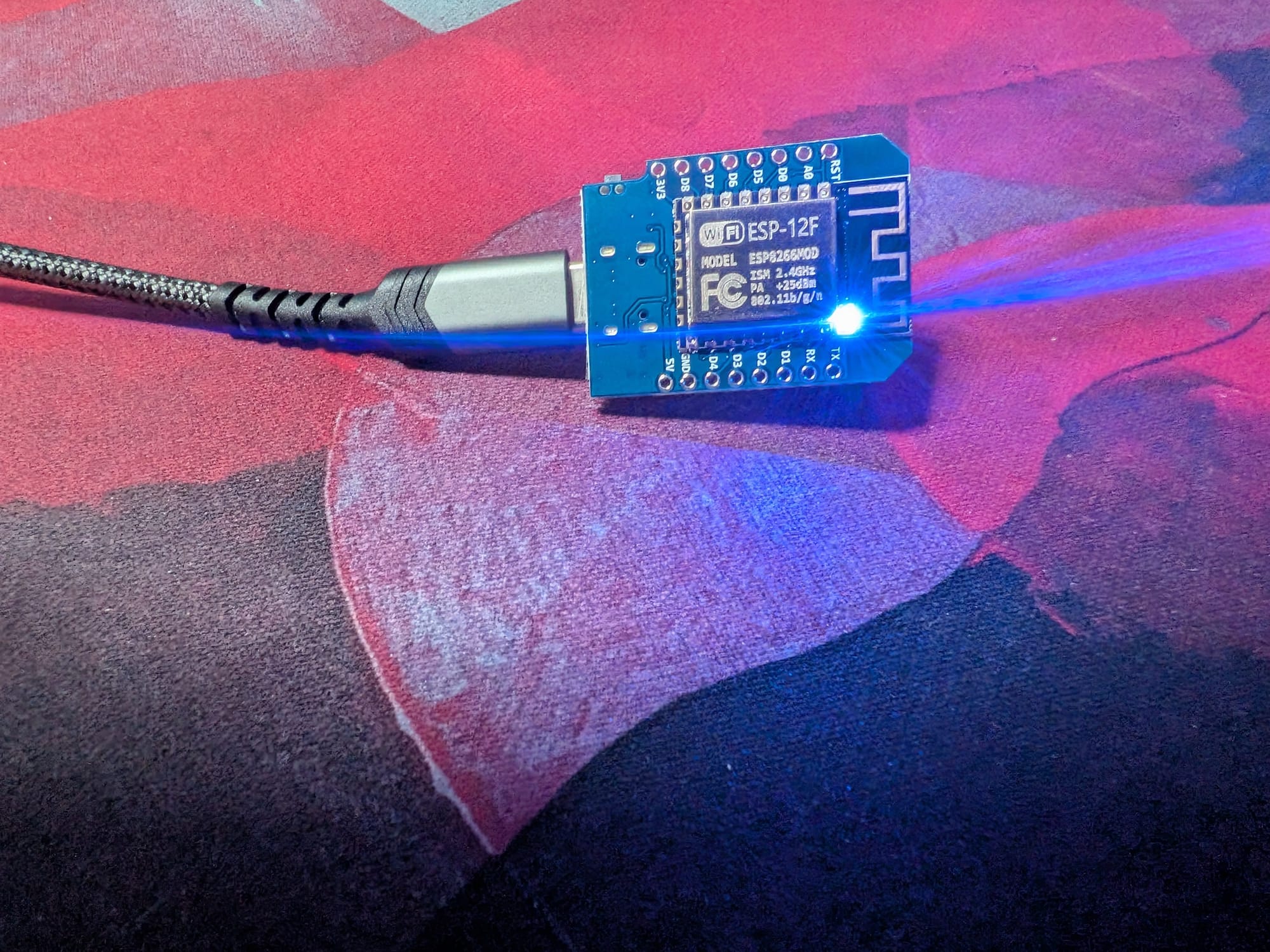
As is tradition I started with testing the ESP8266 D1 Mini Microcontroller by connecting the board [2] and ran the blink sketch:
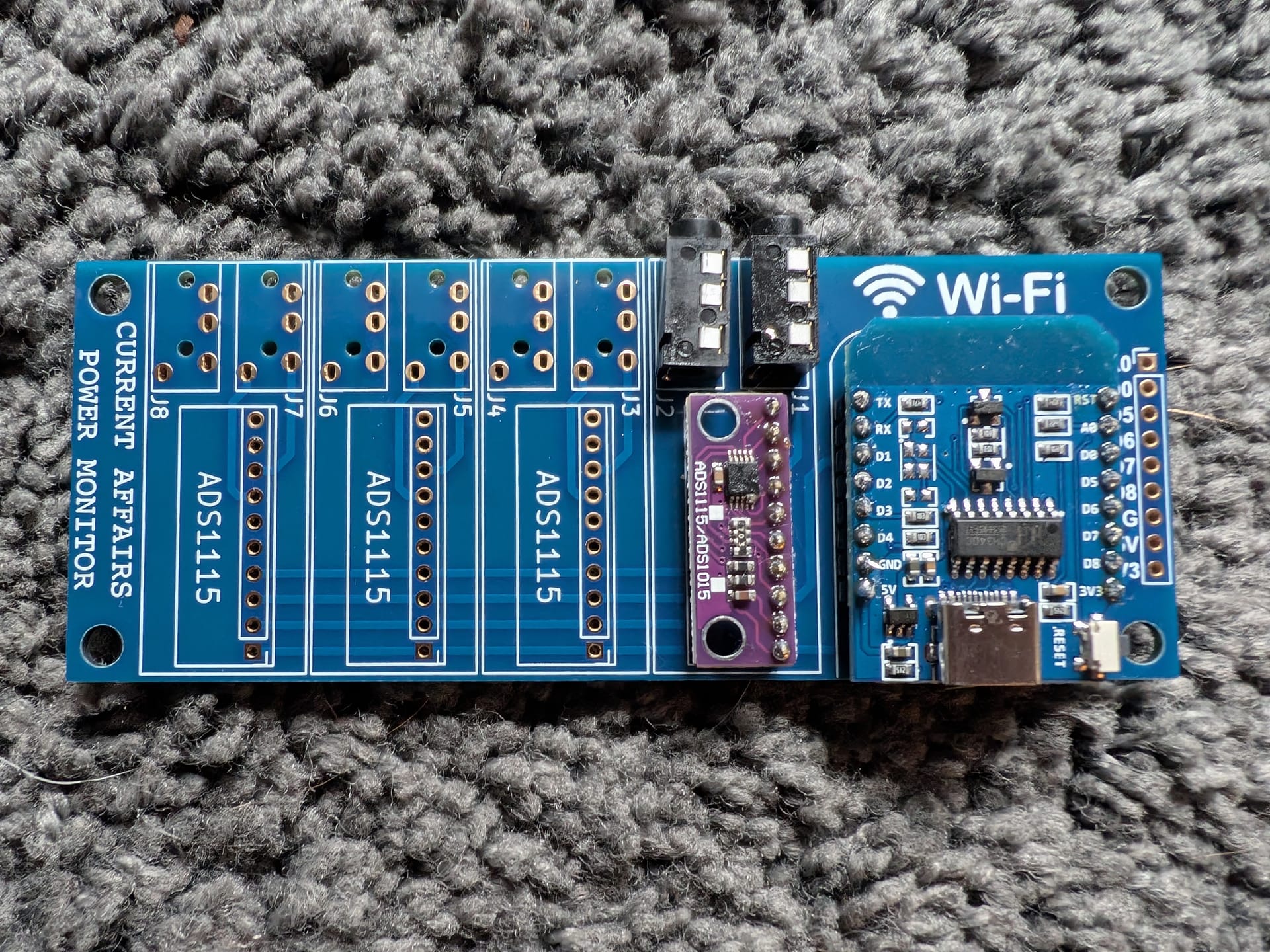
This time I got to solder:
- Two 8-pin headers to the ESP8266 D1.
- The ESP8266 D1 to the PCB. [3]
- A 10-pin header to the ADS1115 Analog-to-Digital Converter Module.
- The ADS1115 to the PCB.
- Two PJ-320A 3.5mm Sockets to the PCB.
Anyways, alcohol wash, apply resin, solder, done. The tips I learned assembling the Thrifty Yeti Locator in HackerBox 0119 really helped out.
The board has space for additional ADS modules [4] and the Analog-to-Digital Converter uses I2C for communication. This makes sense, since we could have multiple ADS chained together that would all need to communicate with the main chip. I2C is a simple way to handle that. This video on the I2C protocol is a great reference and visual aid. Also I should note, I2C is different from the serial protocol I2S that I used in the audio part of HackerBox 0118 - More Human. [5]
However, since I only had the one ADS, I didn't have to change any jumper configurations:
The top input circuit bank (labeled J1 and J2) does not require an address jumper to be closed. For the ADS1115 chip, I2C address 0x48 is selected by connecting ADDR to GND. Leaving all of the jumpers open accomplishes this as well since ADDR has a pull down resistor on the ADS1115 module.
I like your funny words magic man. Trying to discern the transmudane:
- input circuit bank - this doesn't seem like a common term, but this StackOverflow suggests this is a reference to the pins for digital input on the board.
- address jumper - SparkFun and Adafruit saved me here.
- a jumper is used to physically connect two parts of a board and change the behavior.
- In I2C the sub-devices each have an address that is used by the main chip to direct messages.
- So, an address jumper allows you to change the address the a sub-device will use with I2C.
- addr - the address pin.
- pull-down resistor - this tutorial walks through the details, but a pull-down resistor helps bias an input in the correct direction when there is no input.
So putting that all together: When the addr pin is connected to ground the I2C address 0x48 is used. You could do that by connecting address jumper, but because there is a pull-down resistor, the addr pin will be grounded by default. Phew.
OK, here is a second one:
The ADS1115 (datasheet) has an I2C interface and features four single-ended input channels, which can also be configured as two differential input channels. Since our input signals are +/- 1V, we'll be using the input channels in differential mode to capture both the positive and negative portions of the input signal.
Adafruit helped me with this one:
- input channel - used for measuring an analog signal.
- single-ended input channel - measures a channel compared to ground.
- differential input channel - measure the difference between two input channels.
- signals are +/- 1V - the signal is AC and will oscillate above and below 0V.
The missing piece here is that since single-ended input channels are compared to ground, they cannot measure negative voltages. So by using the differential mode we can capture both the positive and negative parts of the wave.
A final piece to decipher:
The ADS1115 incorporates a programmable gain amplifier (PGA). When the PGA is set to 4X gain, the 16 bit sampling resolution represents 0.03125mV per bit.
- a programmable gain amplifier increases an signal (amplifies). They are programmable because the amount the signal is increase can be controlled.
- 4x gain - the voltage is increased by four times.
- 16 bit sampling resolution - the amount of information used to store a reading from the input channels.
- 0.03125mV per bit - the amount of voltage a single bit in the sample represents.
The core part here is the device is taking an analog signal on the input channel, creating a digital reading by sampling. Since the reading is digital, it is discrete and has a fixed number of byte representing the analog value.
Using the Current Affairs Power Monitor
With the theory out of the way, I installed the ESP8266 D1 Mini board library in the Arduino IDE and loaded in the HB0120_SerialOut.ino sketch onto the board. The setup code is pretty simple and the main loop has the interesting parts. For each second the following is done repeatedly to sample the current:
voltage = ads48.readADC_Differential_0_1() * multiplier;
current = voltage * factor;
sum_ads48_0_1 += sq(current);
voltage = ads48.readADC_Differential_2_3() * multiplier;
current = voltage * factor;
sum_ads48_2_3 += sq(current);
The voltage is read from the differential input channel for the positive component of the signal. That voltage is multiplied by the 0.03125mV factor that was mentioned previously to produce the current. The current is then squared and added to a running total to track the sum of the squares. The same is done for the negative component. Additionally, each time a sample is read, a counter is updated.
After a second of sampling has passed, the sum of squares is divided by the sample count to produce the mean. Finally the square root of the mean is taken to produce the root mean square:
I_ads48_0_1 = sqrt(sum_ads48_0_1 / sample_count);
I_ads48_2_3 = sqrt(sum_ads48_2_3 / sample_count);
That's the theory of how the program works, now I had to actually run this. Before I did I double checked to be absolutely certain I had not carved through the shielding of the extension cable.
I plugged the split core transformer into the J1 PJ-320A socket on the board.
I plugged the extension cord into a surge protector.
I plugged a ring light I had into the extension cord.
There was no fire or magic smoke!
I checked the serial monitor and saw some chatter:
J1: 0.001 A (RMS)
J2: 0.000 A (RMS)
J1: 0.001 A (RMS)
J2: 0.000 A (RMS)
J1: 0.001 A (RMS)
I was getting a small reading on J1 even when the light was off. Vampires are real, as evidenced by the standby power draw. Also, as expected J2 was not reading a current since there was no split core transformer plugged into that socket.
When I powered the ring light on, I got a larger reading:
J1: 0.026 A (RMS)
J2: 0.000 A (RMS)
J1: 0.027 A (RMS)
J2: 0.000 A (RMS)
J1: 0.027 A (RMS)
J2: 0.000 A (RMS)
J1: 0.027 A (RMS)
The ring light defaults to max brightness when unplugged. If I reduce the light down to the minimum brightness the device reads:
J1: 0.003 A (RMS)
J2: 0.000 A (RMS)
J1: 0.002 A (RMS)
J2: 0.000 A (RMS)
J1: 0.003 A (RMS)
J2: 0.000 A (RMS)
The ring light can also change from cool to warm light, but that didn't effect the current reading.
The SONOFF Mini R4 Extreme and home power monitoring
The next part of the guide involved the SONOFF Mini R4 Extreme. This is an ESP32 powered device that you can connect to using the "eWeLink-Remote" app. The guide provided a number of videos about using Home Assistant, which I run, and ESPHome, which I am not running yet. [6]
Unfortunately, the guides involve wiring into wall switches, and other parts of your mains. I rent and my landlord literally will not even let us touch anything on the toilet that is constantly failing. Alas, I had to skip this part for now, but I will tuck the Mini R4 Extreme away for a future project.
The ESP-01S Wi-Fi Relay Module
This section of the guide was extremely brief. The box included a USB to TTL board that can be connected to the ESP8266 ESP-01S Wi-Fi Relay Module by cables. They also provide a relay for connecting to the mains. One project involves making a wired doorbell smart. Unfortunately, the doorbell at my apartment barely works. I will tuck this away as well.
Final thoughts:
The guide ends with a remembrance of Thompson, Kernighan, and Ritchie. This was a nice sentiment, but they didn't connect it to anything else from the box. Overall though I think this months box was pretty good. I won't deduct points because I am a renter and not an owner. I also appreciated how different the projects felt this time compared to the other two boxes I had tried.
RMS is an old friend of mine, since its used when calculating some HRV statistics from inter beat intervals. ↩︎
Everything is USB-C in the future. ↩︎
The ESP8266 came with female to male headers as well. So I could have instead soldered those to the PCB and then slotted the ESP8266 in. However, I don't see myself using that ESP8266 for another project. ↩︎
You have to grab the parts yourself though. ↩︎
So many protocols to learn. ↩︎
In fact I've been thinking about trimming back how many services I self host to reduce the management burden. ↩︎
Member discussion