Review of HackerBox 0118 - More Human
I want to tackle a couple electronics projects in the future and I need to shake the rust off. Rather than destroy some expensive parts trying to remember how to solder I thought I'd practice a bit first. Get some repetitions in. So I searched around to see if there were any monthly project kits and I found HackerBoxs. Their philosophy seems to match what I am looking for:
The goal is progress, not perfection. You’d better plan on messing some things up. We all do it. The more components that you burn up, short out, or otherwise mutilate, the more you are learning. The path to expertise in electronics is beset with smoking heaps of gear and dreadful tangles of spaghetti code and cables. If such frustrations might tempt you to take up hateful words against, or place blame upon, your humble kit vendor, perhaps a less demanding hobby should be on your horizon.
The first subscription box that came in was "HackerBox 0118: More Human". The project is built around working with a Raspberry Pi Pico 2 W and some audio equipment. The instructions for each box are posted on Instructables. I want to avoid just repeating the instruction, so instead this is a collection of my thoughts on the experience.
Using a Raspberrry Pi Pico 2W as an Arduino
Before any of the soldering there was an intro to the RPi. The instructions point you to go through most of this Random Nerd Tutorial.
The instructions talk about working with Arduinos, but the box supplied a Raspberry Pi. I wass confused, because I've worked with RPis before and they are not Arduinos. See:
- BirdNet-Go: But We Have Bird Monitoring At Home
- Media Center Series Part 2: Wireguard with Docker on Raspberry Pi 4
- Media Center Series Part 3: Simpler Raspberry Pi 4
That's what I thought at least. However, the Arduino Pico project provides Arduino cores [^ See https://thelinuxcode.com/install-arduino-core/ for an explanation of what that means.] for all the Pico boards.
The guide they linked was pretty quick. The most useful part was how to configure the Arduino IDE to work with the 3rd party core. Other than that I learned how to put the board into bootloader mode and test out the example blink sketch.
After that the instructable led me through running the ScanNetworks and HelloServer sketch examples. [^ I also found a BLE scan example sketch, which is part of what I want to do in a future project.] The kit had a USB-C to Micro USB adapter for the RPi. I appreciated they wanted everything included, but I already had several so that felt a bit wasteful. [^ I understand though that packing different versions of the boxes would increase cost and complexity for them. Hopefully we will one day reach the point where everything is USB-C in the future.]
Some notes for using the Arduino IDE on NixOS
There is the arduino-ide package in nixpkgs that you can use, as well as arduino-cli. [^ I also saw a arduino-language-server, so I suppose you could use a different IDE if you wanted.] Connecting to the board, verifying the sketches, and uploading them all worked without issue. I had trouble with debugging and serial communication though. Debugging would flash the error message:
OpenOCD: GDB Server Quit Unexpectedly. See gdb-server output for more details.
The Arduino IDE would log:
Waiting for gdb server to start...[2025-09-09T17:42:38.931Z] SERVER CONSOLE DEBUG: onBackendConnect: gdb-server session connected. You can switch to "DEBUG CONSOLE" to see GDB interactions.
/home/ciferkey/.arduino15/packages/rp2040/tools/pqt-openocd/4.1.0-1aec55e/bin/openocd -c "gdb_port 50000" -c "tcl_port 50001" -c "telnet_port 50002" -s /tmp/.arduinoIDE-unsaved202589-6015-1te8pwb.6ymo/ScanNetworks -f /nix/store/07imna35mjq5bjwp22rknx9a1amh5ayx-arduino-ide-2.3.6-extracted/resources/app/plugins/cortex-debug/extension/support/openocd-helpers.tcl -f /home/ciferkey/.arduino15/packages/rp2040/hardware/rp2040/5.0.0/lib/rp2350/picoprobe_cmsis_dap.tcl
Open On-Chip Debugger 0.12.0+dev-gebec9504d-dirty (2025-05-30-21:52)
Licensed under GNU GPL v2
For bug reports, read
        http://openocd.org/doc/doxygen/bugs.html
CDRTOSConfigure
Info : Hardware thread awareness created
Info : Hardware thread awareness created
Info : Hardware thread awareness created
Info : Hardware thread awareness created
cortex_m reset_config sysresetreq
Info : Listening on port 50001 for tcl connections
Info : Listening on port 50002 for telnet connections
Error: unable to find a matching CMSIS-DAP device

[2025-09-09T17:42:38.988Z] SERVER CONSOLE DEBUG: onBackendConnect: gdb-server session closed
GDB server session ended. This terminal will be reused, waiting for next session to start...
I was not able to resolve this issue yet. I also had trouble connecting to the serial plotter until I added my user to the dialout group.
Finally some soldering
Space is at a premium in my apartment, so I don't have a good work bench yet. In fact, up until recently all I had was a Pinecil v2 I bought years ago and never opened. [^ I already had an Anker GaN charger that supplied enough power.] Last week I went to Micro Center to get solder, wick, a brass sponge, wire cutters and a fume extractor. [^ I already had safety glasses.] With that I was able to sit down and start soldering.
This kit was set up so that you added headers to the components and used jumpers to connect them. I appreciated that, since I could reuse the parts in the future for other projects. The soldering comprised of adding:
- Two 20-pin headers on the Raspberry Pi Pico 2 W
- One 4-pin header on a TRRS breakout module.
- One 5-pin header on a PAM8302A speaker amp.
- Strip and connect the speaker wires to the amp.
- Two 3-pin headers on an I2S Microphone Sensor Module
I was able to do most of them without issue. The instructable stated to "Insert the headers and hold the pins perpendicular to the module PCB" and "Solder the header pins into place". That felt janky, so I went searching and found this video about soldering Header Pins to Your Raspberry Pi Pico which suggested using a breadboard to hold everything in place. That approach worked really well.
The only board that gave me trouble was the microphone. For some reason the solder kept sticking to my Pinecil's tip rather than attaching to the board. Some internet searching suggested this could be from the iron's tip oxidizing, but I still had trouble even after cleaning the tip on the brass sponge.
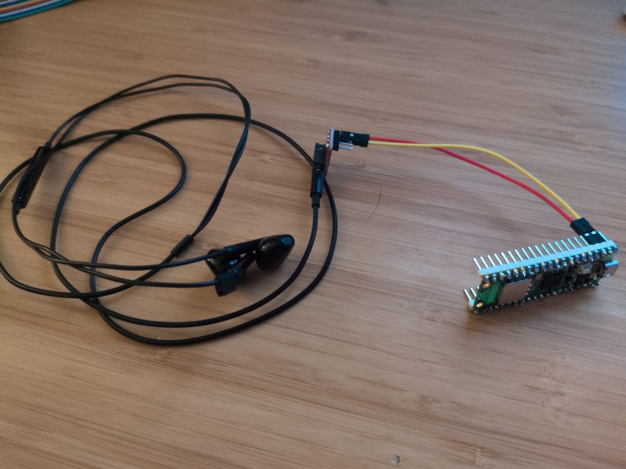
The pulse-width modulated audio experiment
The first experiment was outputting sound. You connect the TRRS breakout board [^ Also cool, sparkfun has a very similar board with a repo on github https://github.com/sparkfun/TRRS_3.5mm_Jack_Breakout/ under Creative Commons!] to the Pico and plug in headphones. [^ This was another part that makes sense to include, but felt wasteful since I already had ones I could use.] Alternatively, you could connect the amp/speaker combto. Then you loaded the PWMAudio/PlayRaw.ino example sketch. [^ You can see that sketch here.] Shame on me for not reading the sketch first before running, because I blasted my ears with the Macarena.
While the instructions told you what to do, they didn't really talk about why you did anything. For example, they don't say why we wanted to use the tip and ring1 pins on the breakout board. [^ There was a link with the text "TRRS" but the anchor had no source.] The wikipedia page for TRRS gave a good explanation though: "Tip, Ring, Ring, Sleeve" is for a stereo headset with mono microphone. Mentioning that:
Two different forms are frequently found. Both place left audio on the tip and right audio on the first ring, same as stereo connectors. They differ in the placement of the microphone and return contacts.
Finally the instructions mention you are using pulse width modulated audio, but doesn't define that. I found this video explains PWA clearly.
The audio sampling experiment
The next experiment was recording sound from the microphone. They link to the data sheet for the board, but say nothing else. I found this great video on how to read a datasheet.
There are also lots of terms in the section that don't have definitions. The board communicates of I2S, and the instructables says that:
allows the INMP441 to connect directly to digital processors, such as DSPs and microcontrollers, without the need for an audio codec in the system.
I've recently started reading The Hardware Hacking Handbook [^ Which is available DRM free: https://nostarch.com/hardwarehacking], but paused after realizing I needed to learn some basics first. I remember the book mentioning I2S interfaces, and I wanted to know more. The first part of this video provides a good introduction to how the protocol works.
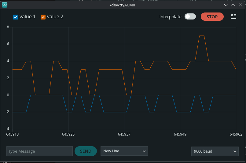
For the first part of the experiment, you load the I2S/I2SInput.ino example sketch [^ You can see that sketch here https://github.com/earlephilhower/arduino-pico/blob/master/libraries/I2S/examples/I2SInput/I2SInput.ino.] and use the serial plotter in the IDE to see the audio.
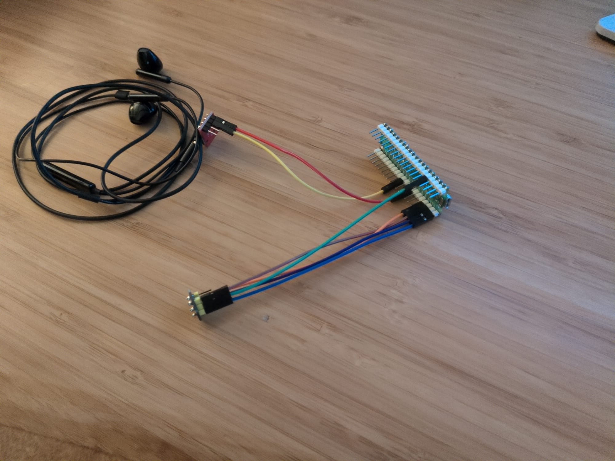
Next, you reconnect one of the audio output devices. Then you use a echo.ino sketch they provide which plays back the input from the mic. I got a pretty garbled audio output when I ran this. I'm not sure if that's a limitation of the hardware or not.
The kit also included a USB-C to 3.5mm DAC which you do not use in the projects. Perhaps they included it so you can use the headphones on modern devices?
The Edge AI model and GenAI experiments
I guess this is where the "More Human" part comes in.
First, the instructable talks a bit about what edge models are. Then, they show you a project on Edge Impulse for audio keyword detection. If you sign up for a free account you can make a build for the Pico 2 W and try the project out. Finally they provide a list of resources for further reading. This part was interesting since you can see the pipeline from start to finish.
Finally, they give a short summary of GenAI. There is no project component for this section. To be honest, this section felt a little tacked on.
Final thoughts, followups, and the next box.
The box fulfilled my goal to practice and learn about electronics, albeit in an expensive way. Two things I would like to try are:
- practice rewriting some sketches in python using MicroPython.
- practice rewriting some sketches in rust using Embassy
After this box I was actually going to cancel the subscription, but I was not quick enough. However, the next box that's on the way right now looks to be related to GPS, which is exactly what I want to work with in a future project. So I guess that all worked out for me. I'll try to review that box too.
Member discussion